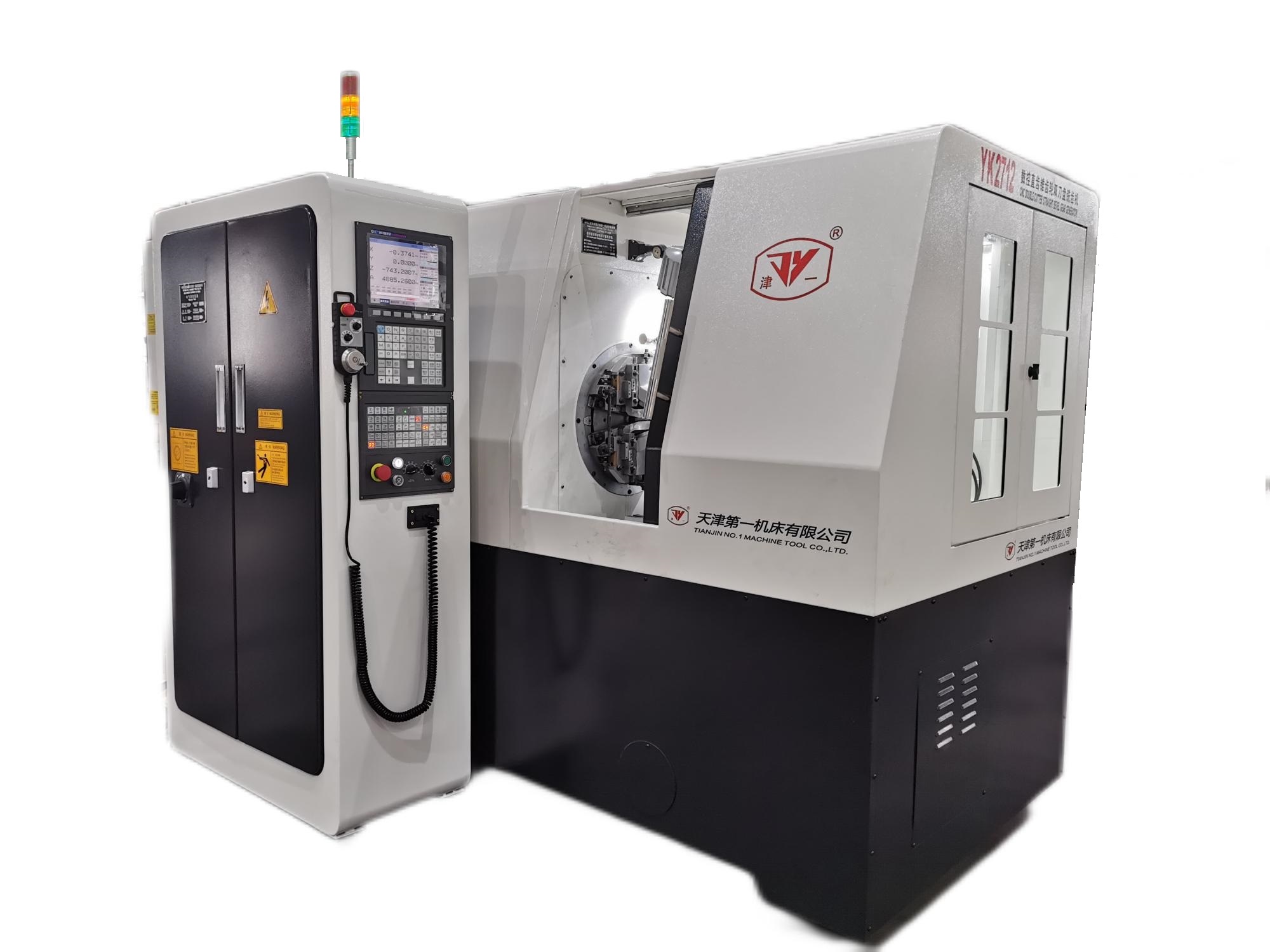
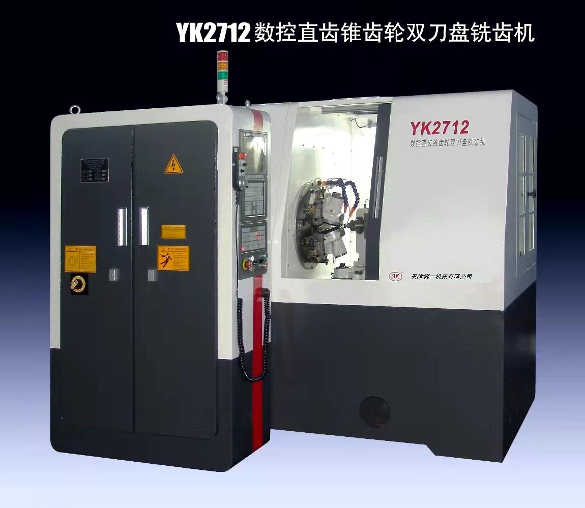
YK2712数控直齿锥齿轮双刀盘铣齿机
YK2712型数控直齿锥齿轮双刀盘铣齿机床,是天津一机集七十年生产直齿锥齿轮机床、弧齿锥齿轮机床专业技术经验而研发成功的作品。
特别适合加工齿向为鼓型的齿,用于粗切、精切直齿锥齿轮。加工效率快,比同规格刨齿机效率高约3-5倍,噪音低。机床加工精度达GB 6级。
该机床适用于加工直齿锥齿轮传动的变速箱、减速机、精密传动齿轮等。
机床主要性能和结构特点
1、本机床采用国产广数GSK218MC-V数控系统。可根据客户需求使用德国西门子(SIEMENS)或日本发那科(FANUC)数控系统及电机,实现四轴控制三轴联动。主轴伺服电机控制刀轴主驱动无级调速,可实现电子手轮对刀及辅助调刀。
2、本机床双刀盘支架部件结构布局独特,保证在高刚性能下合理空间尺寸。
3、本机床摇台及工件箱均采用高精度蜗轮付传动,结构及传动均采用高刚性设计。
4、本机床主要电气件、轴承及密封件均采用进口件,保证机床可靠性。
5、本机床配置独立密封电气柜具有恒温控制装置。
6、本机床配置安全防护罩。
7、本机床配置铁屑排屑器(选配)。
机床主要技术参数
加工工件模数范围 | mm | 2.5~0.5 | |
最大工件锥距 | mm | 60 | |
轴交角为90°时,工件的最大传动比 | 1 : 10 | ||
最大工件直径 | mm | 125 | |
最大工件齿宽 | mm | 11 | |
工件齿数范围 | 5~150 | ||
刀架最大调整角 | 7.5° | ||
工件箱主轴端面至机床中心距离 | mm | 20~190 | |
加工每一齿所需的时间 | s | 4~20 | |
刀具切削速度 | m/min | 40-60 | |
工件主轴锥孔大端直径 | mm | 31.267 | |
工件箱主轴孔锥度 | 莫氏四号 | ||
刀盘直径 | 6″(152.4mm) | ||
摇台最大摆动角度 | 零刻线以上 | 30° | |
零刻线以下 | 30° | ||
主电机功率 | KW | 2.3 | |
主电机转速 | rpm | 800~1500 | |
冷却泵电机功率 | KW | 0.42 | |
冷却泵流量 | L/min | 200 | |
主机电压 | v | 380 | |
机床总功率 | KVA | 10 | |
机床净重 | T | 2 | |
机床外廓尺寸 | mm | 1700x1650x1700 | |
YK2712 CNC DOUBLE-CUTTER STRAIGHT BEVEL GEAR GENERATOR
The YK2712 CNC double-cutter straight bevel gear generator is a newly developed product of Tianjin No.1 Machine Tool Co., Ltd. through its specialized technology and experience in building straight bevel gear cutting machines and spiral bevel gear cutting machines for nearly 70 years.
The machine is designed for rough cutting or finish cutting straight bevel gears and it’s especially suitable for cutting gears with crowned teeth. The machining efficiency is very high, about 3 – 5 times higher than machines of the same specifications, and the machine noise level is low. The machining accuracy of the machine can reach Grade 6 of the GB Standard.
The machine is suitable for cutting straight bevel gears used in gear boxes, speed reducers, precision transmissions, etc.
MACHINE FEATURES
1. A GSK218MC-V CNC control system or a SIEMENS control system (Optional) a FANUC control system (Optional) is equipped on the machine and this is a 4-axis CNC machine with 3- axis simultaneous movements. A spindle servo motor controls the stepless speed regulation of the cutter spindle. Tool setting and cutter adjustments can be performed through the electronic handwheel.
2. The structural layout of the double cutter brackets is unique to guarantee a reasonable space in the high rigidity conditions of the machine.
3. Both the cradle and the workhead are driven by means of high precision worm and worm wheel pairs. All the structures and the transmissions of the machine are rigidly designed.
4. All the CNC control system, the major electrical components, the bearings and the sealing parts are imported ones to ensure the reliability of the machine.
5. The machine has a free-standing sealed electrical cabinet equipped with a thermostatic-control device.
6. A full- enclosure is equipped for the machine.
7. A chip conveyor (Optional) is available for the machine.
SPECIFICATIONS
Max. module of work | mm | 2.5 –0.5 |
Max. cone distance of work | mm | 60 |
Extreme ratio (at 90º shaft angle) | 10:1 | |
Max. diameter of work | mm | 125 |
Max. face width of work | mm | 11 |
Teeth number | 5 --150 | |
Max. adjusting angle of cutter head | ±7.5º | |
Distance between face of work spindle and machine center | mm | 20 -- 190 |
Time for cutting one tooth | s | 4 -- 20 |
Cutting speed | m/min. | 40 -- 60 |
Diameter of taper hole of work spindle at large end | mm | 31.267 |
Taper of work spindle hole | Morse #4 | |
Cutter diameter | 6” (152.4mm) | |
Max. cradle roll | above zero line | 30º |
below zero line | 30º | |
Power of main motor | kw | 2.3 |
Speed of main motor | rpm | 800 -- 1500 |
Power of coolant motor | kw | 0.42 |
Flowrate of coolant pump | l/min | 200 |
Total power of machine | kva | 10 |
Net weight | t | 2 |
Overall dimensions | t | 1700 x 1650 x 1700 |
Voltage v 380


